Neutron Diffusion Time Measurement
Author: Luke, Scott & Tim
INTRODUCTION The question has been asked if typical 3He detectors or other pulse-based electronic radiation measurement systems are appropriate or even capable of directly measuring neutron production in pulsed systems while being insensitive to the transient havoc created by the pulsed system. The answer is yes. Many amateur nuclear fusion experimenters are interested in impulse driven deuterium-deuterium reactions heated by electromagnetic compression. Characteristic time scales of their systems range from 1 to 10us, and typical peak neutron production ranges from 106 to 108 neutrons per second in an isotropic distribution. The peak currents required, described in denominations of kiloamperes, are supplied by high voltage energy storage capacitor banks initially charges to tens of thousands of volts. These pulsed power systems’ switching initiation, plasma generation and coupling, and subsequent ring down are all rapid processes fraught with electrical transient noise that can interfere with standard low-level signal processing NIM instrumentation. Additionally, the response of the NIM electronics to the detection of a genuine nuclear event results in a deadtime on the order of 10us or longer. One can then imagine a pulsed experimental scenario in which the pulsed-power transient triggered the NIM counting electronics and masks the registration of a true nuclear event within its 10us window, implying typical NIM-based apparatus is unsuitable for measurement. Other methods, such as foil activation or superheated emulsion bubble detectors are seemingly now the only option. This paper describes a pulsed neutron experiment to demonstrate that a 3He NIM based neutron detection is still a viable method due to the neutron diffusion time in a polyethylene moderator.
Although the neutron production window may be short (10us or less), the neutron transportation time from the source to the detector is relatively long, with a characteristic time of 100us, which affords the pulsed plasma experimenter the opportunity to “look” for neutrons in the quiescent period after the pulsed event.
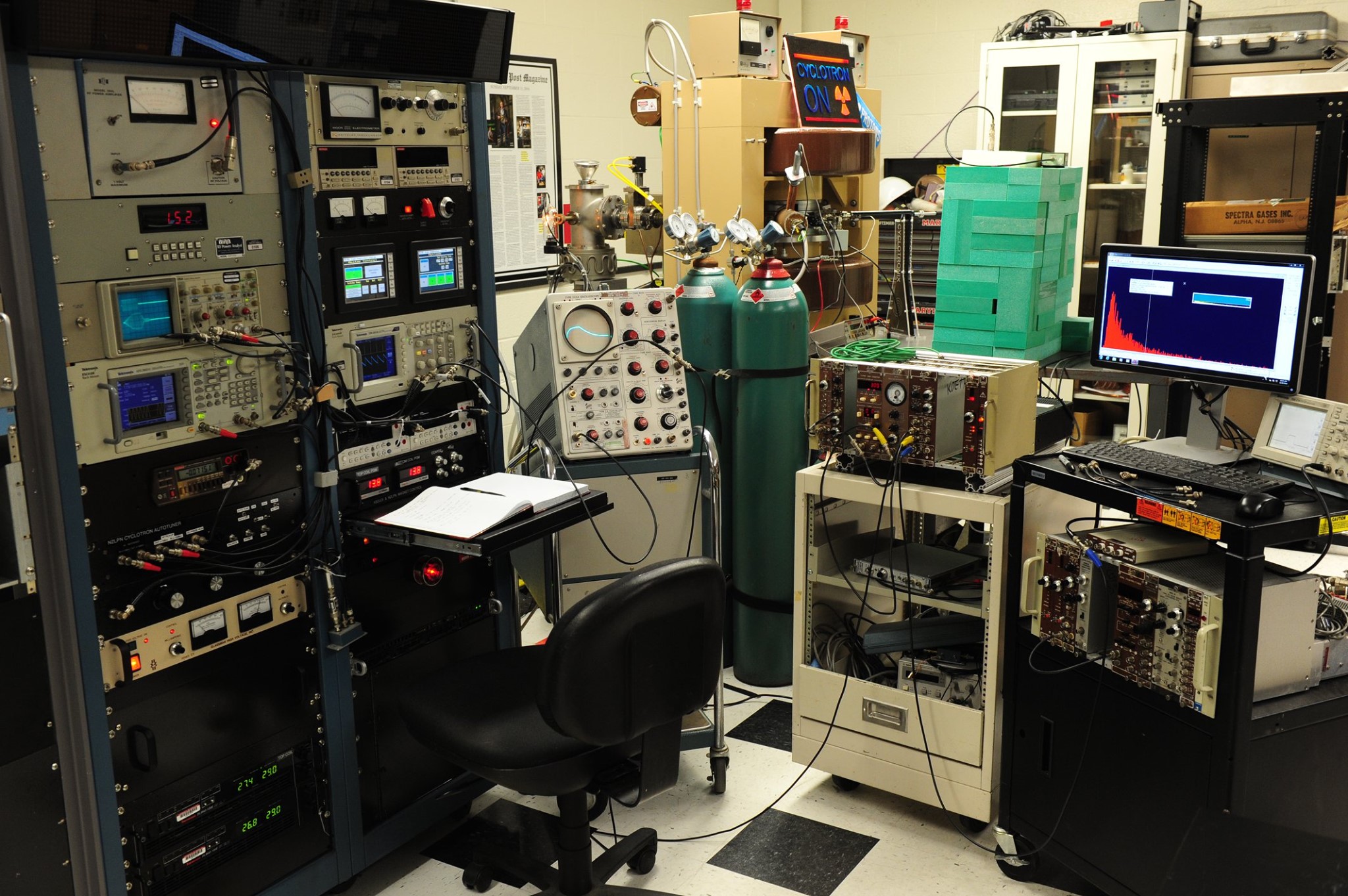
EXPERIMENTAL SETUP: The 12-inch cyclotron was tuned up for D+ ions, with the RF system tuned to 7.150MHz, for an average magnetic field set to 0.96T (by setting the top coil to 29.007Amps and bottom coil to 29.121 amps) with the AKG270 spiral poletips.[1] The ion source used the largest rectangular aperture chimney (hence lowest pressure differential), the Mass Flow Controller was set to 0.230 scc/m for an operating pressure of 3E-6 Torr, the ion source was run with a 10mA arc discharge current – all of these parameters balanced for optimal operating point. Beam tune up was verified with ~8 kV on the internal deflection (Wien filter) confirming successfully acceleration of deuterium.
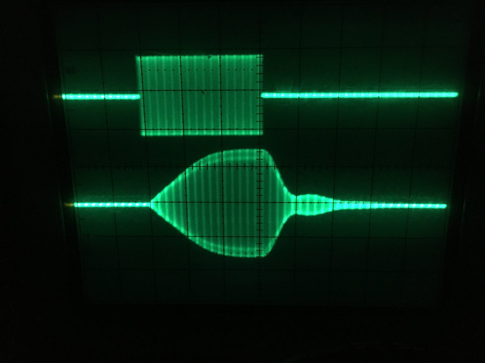
The typical 12-inch cyclotron configuration to produce D-D neutrons through beam-on-target operation uses a long-pulsed mode with a duty factor of about 10% for RF thermal considerations given the passive cooling of the RF matching box components. However, the heretofore “pulsed mode” operation typically used beam-on durations of order 150ms – a lifetime as far as nuclear processes go. For the measurement at hand, the cyclotron was pushed into its shortest pulsed mode operation yet, with only 230 RF cycles at 7.15 MHz (an RF drive pulse of 30 us duration), which resulted in the generation of a 10us beam-on-target pulse after the 20us ring up time. With such a short pulse duration, the pulse repetition rate could safely be increased up to 200pps (200Hz). Figure 2 shows the RF pulse structures on an oscilloscope with a time base of 10us/div: the upper trace is driving RF pulse, lower trace is actual DEE voltage, note the ring-up-time is due to the high Q of the tank circuit.
NEUTRON PRODUCTION: It was important that not more than a single neutron would be registered in the detector per cyclotron RF pulse – placing a limit on the peak neutron production. Neutron production rate can be controlled by selecting the energy of the incident deuteron beam by adjusting the radial placement of the deuterated target by means of a linear motion feedthrough.
The target was position for a nominal 100keV incident deuteron beam energy (r=0.067m). After being positioned, the 3He detector was calibrated by placing a NIST calibrated 252Cf sealed neutron source at the face of the deuterated target, thus giving the ability to quantify peak neutron production from the cyclotron during operation. Care was taken not to disturb the 3He detector geometry to maintain the calibration. During a 5 second CW run of the RF at full operating power, the DEE voltage and ion source production rate were adjusted for an average neutron production of 500,000 neutrons per second, which were considered to be isotropic.
When operating in this fast cyclotron-pulsed mode with a 10us duration of beam-on-target time, an average of 5 D-D fusion neutrons were produced. During most cyclotron pulses, these neutrons would completely miss the detector altogether, with approximately 1 out of 250 cyclotron pulses registering a neutron. The likelihood of more than one striking the detector per cyclotron pulse was vanishing small. This was crucial to the measurement.
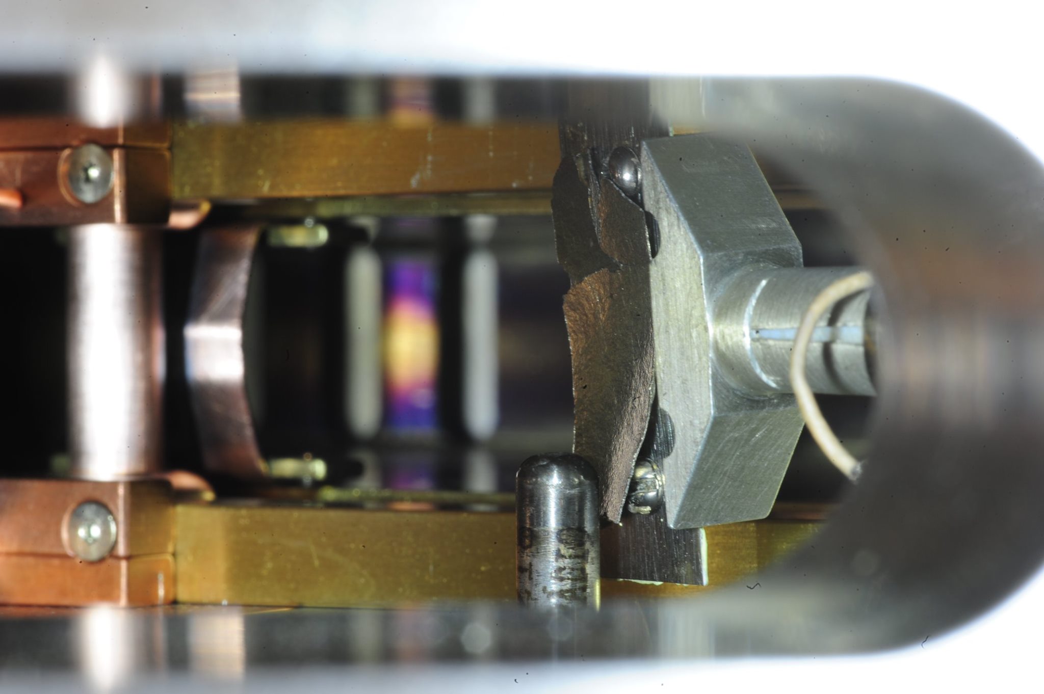
NEUTRON DETECTION: The neutron detector consisted of a ~2-foot-long 3He tube nested within a stack of pure polyethylene blocks. The two sides and back were stacked with neutron absorbing borated poly blocks to set boundary condition.
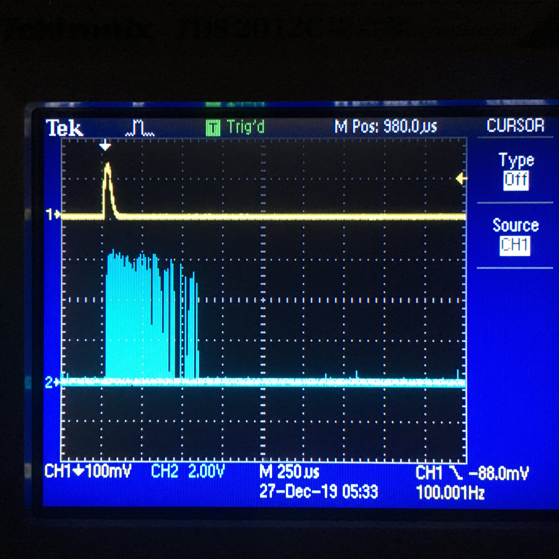
A preliminary demonstration of the neutron diffusion effect is given by a digital oscilloscope set to infinite persistence which recorded the electronic pulses generated from the detection of neutrons over numerous cyclotron pulse events. Figure 4 displays the long times up to which a neutron may take to arrive at the detector. The upper yellow trace in figure 4 is the rectified reference of the actual RF “on time” pulse (the blip on the upper yellow trace), hence the cyclotron pulse is the only time in which neutron can be produced. The lower blue trace displays the pulses from the 3He detector NIM electronics, which are seen to continue to arrive long after the cyclotron RF is off. After 5 minutes of acquisition at 100 pulses per second a total of 250 neutrons events are observed. One can see the slowest neutron took 550us after production (RF off) to reach the 3He detector.
This
is not a quantitative measurement, since many of the neutron detector pulses
overlap and blur their individual arrival times. However, even from this quick glance, one can
observe a higher density of detection events immediately after the cyclotron
pulse, and the number of detection events begin to thin out with elapsed time
from the cyclotron-on pulse, after which there is a point that neutrons are no
longer detected. This implies an exponential probability with a characteristic
time of the diffusion.
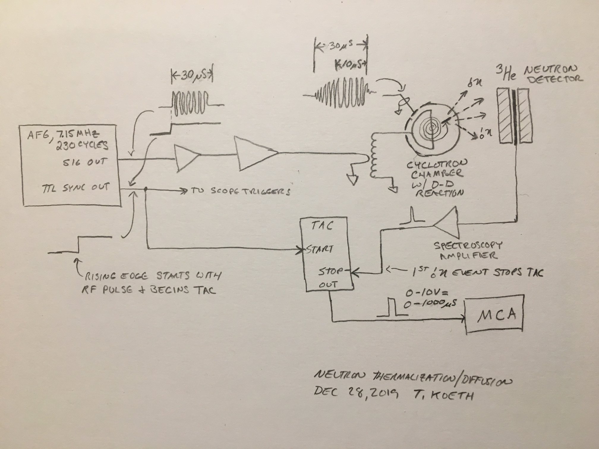
To quantify
the thermalization and diffusion time, an Ortec model 567 time-to-amplitude-
converter (TAC) was employed as outlined in figure 5. The TAC converts a time period, initiated
(start) and subsequently terminated (stop) by electronic pulses within a
preselected time window. In the present
case, the full-scale time window was set 1ms.
The TAC then delivered a proportional output pulse, ranging from 0 to
10V, corresponding to a time period of 0 to 1ms. Thus, if the period between the start and
stop pulse was 500us, then the TAC would then output a 5V pulse. The TAC output was then binned by a
multi-channel analyzer (MCA) to generate the temporal profile. The MCA used was
an Ortec EZMca set to a conversion gain of 512 channels. If the time between
start and stop pulses exceeded 1ms, the TAC simply reset without triggering an
output pulse, and awaited a new start pulse, thus ignoring cyclotron pulses
that did not result in a detected neutron.
A ten-point calibration of MCA channel-to-time interval calibration of
the TAC-MCA system was performed with 70, 100, 200, …, 900uS time intervals generated
from a Tektronix arbitrary waveform generator. To perform the measurement of
neutron thermalization and diffusion time, a TTL pulse synchronized with the
beginning of the RF pulse started the TAC clock, and the NIM pulse arising from
the 3He detector registering a neutron provided the stop pulse. These two signals form the basis of the
measurement. The RF pulse consisted of a
20us ring-up time, followed by a 10us flat top, during which an average of 5
neutrons were produced. The neutron
propagation from the target, through the chamber wall, through approximately 8
inches of air, and then finally diffusing through the polyethylene before
entering the 3He is the measured quantity. That process, presumably dominated by the
duration spent in the polyethylene is long compared to the 10us RF pulse (the
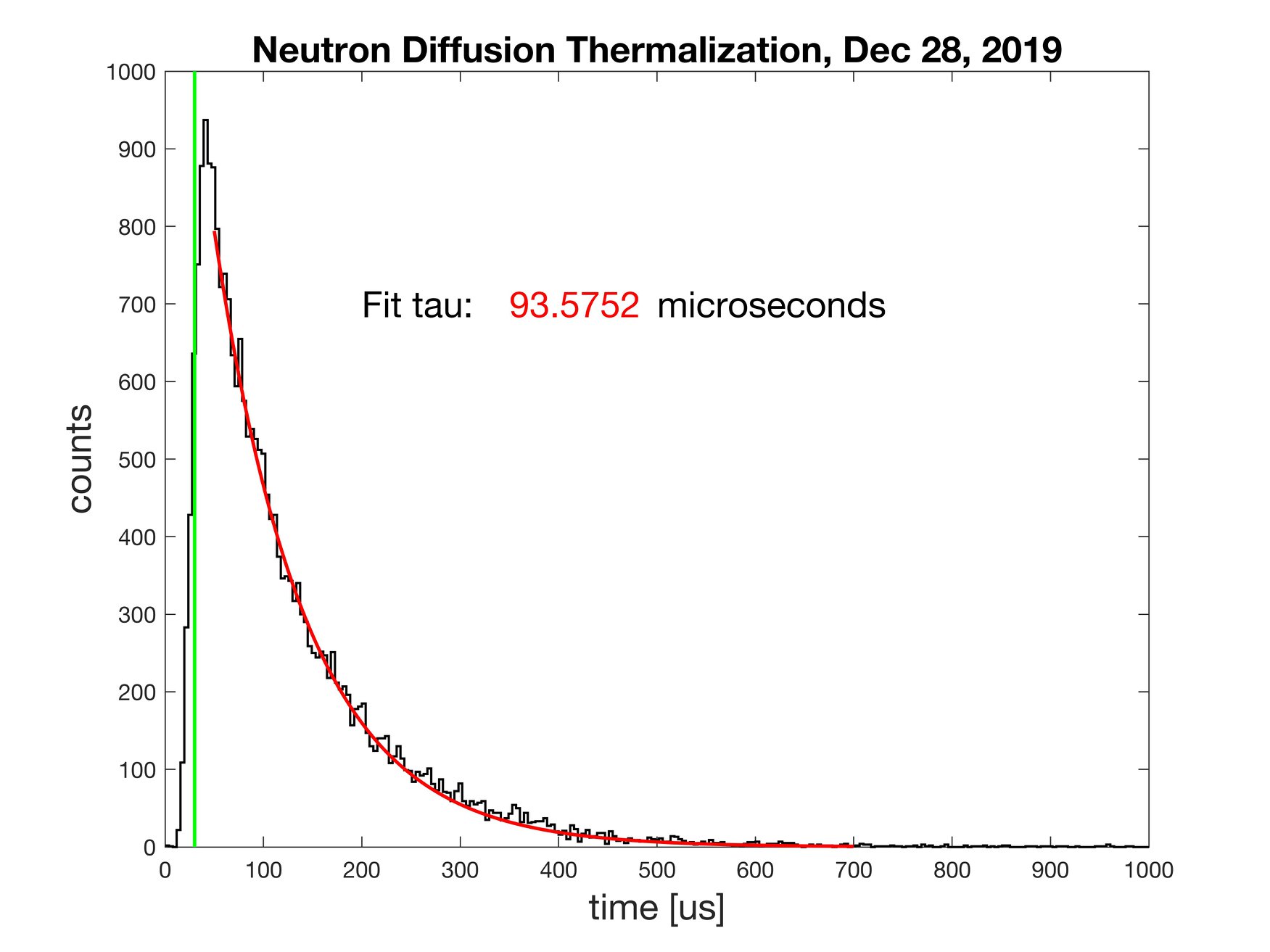
time window in which a neutron could be produced). The multichannel analyzer’s
binning created a histogram of cyclotron pulse-neutron detection time intervals
over a 1-hour period of acquisition, or 720,000 cyclotron pulses. Figure 6
shows a fit to the data, yielding a measured diffusion time of approximately
94us.
To understand the background, we performed an acquisition run of five minutes of neutron events were collected with all cyclotron systems operational, including the pulsed RF, except the ion source discharge power supply was shut off and no neutrons were detected during that time.
REFERENCES
[1] Koeth, T.W., Undergraduate Education With the Rutgers 12-Inch Cyclotron, Physics Procedia, Volume 66, 2015, Pages 622–631
[2] Timothy W. Koeth, Neutron Production with a 12-Inch Cyclotron, November 18, 2017
[3] K. Ruisard, G. Hine, T.Koeth, A. Rosenberg, “The Rutgers Cyclotron: Placing Student’s Careers on Target,”
[3] J. G. Beckerley, “Neutron Physics – A Revision of I. Halpern’s Notes on E. Fermi’s Lectures in 1945,” AECD- 2664, Oct 16, 1951
[5] V.A.Livanov, A.A. Bukhanova, and B.A. Kolachev, “Hydrogen in Titanium” Israel Program for Scientific Translations, Jerusalem 1965. Part 3, Chapter 1