Pulsed B-Dot Measurement
Author: Tim
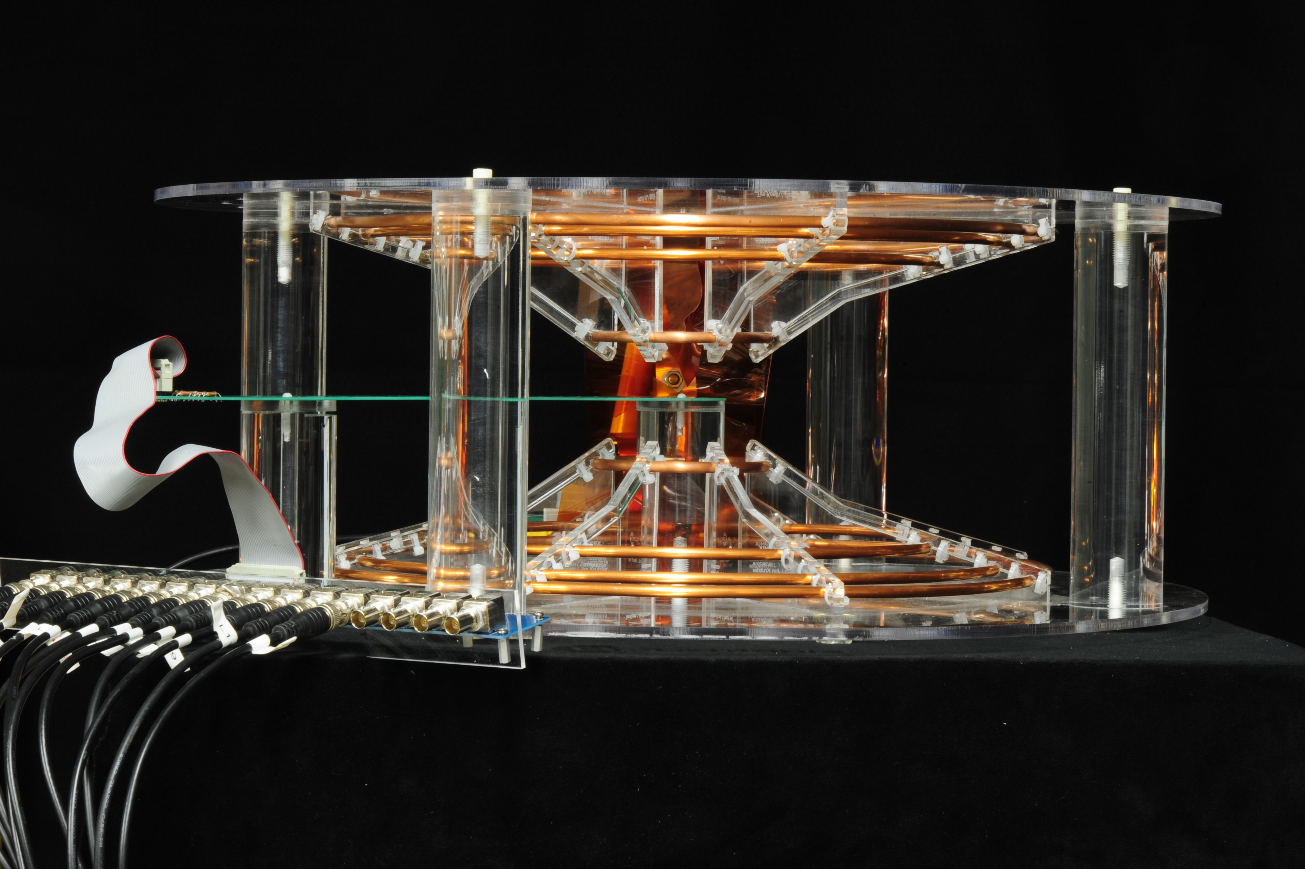
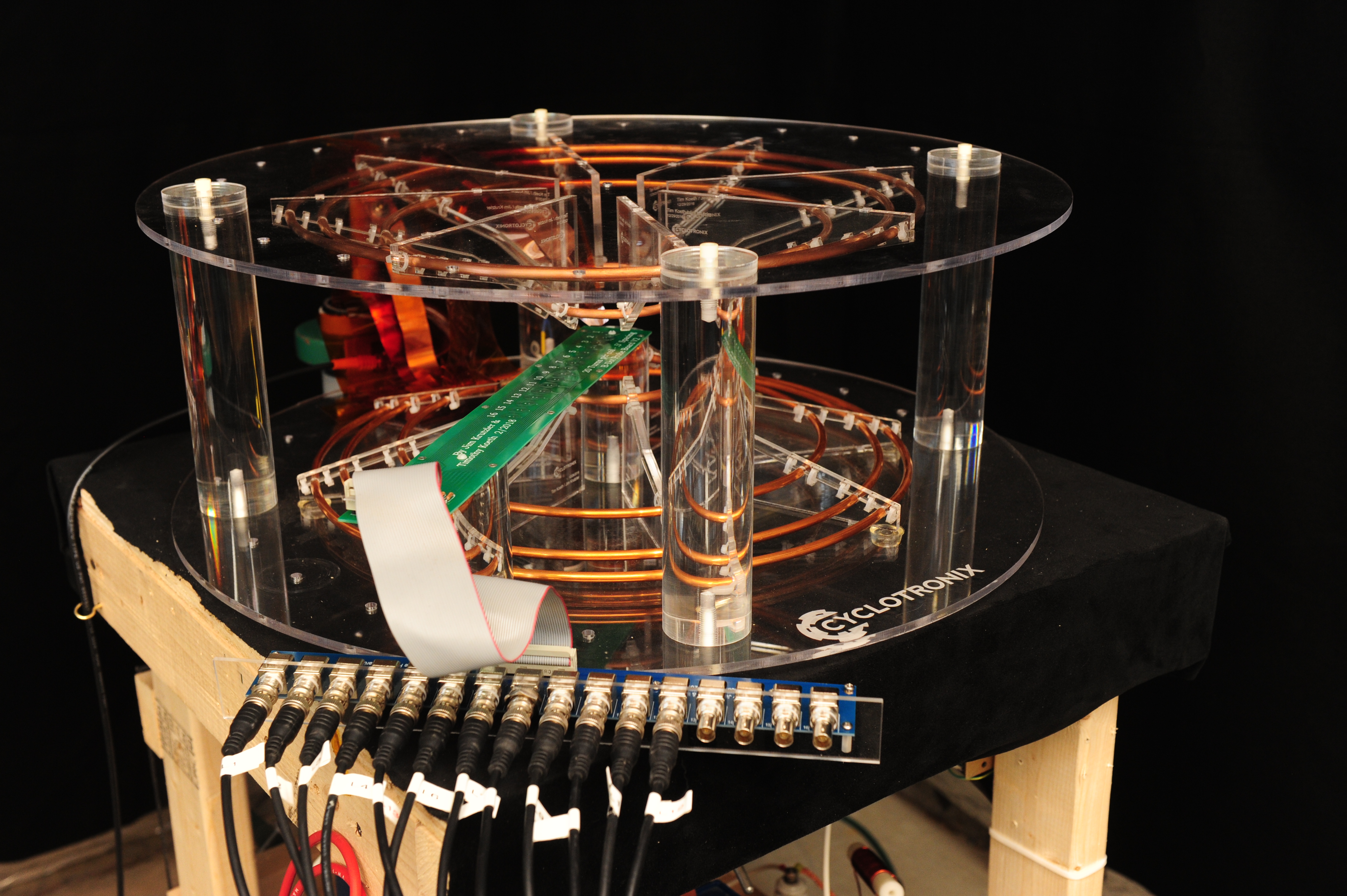
After construction of the betatron coil form it was necessary to verify the field profile. Because of the few number of windings it was impossible to energize the coils with a sufficient DC current so as to perform a typical Hall Probe raster scan. A pulsed current method of measuring was needed. The actual betatron pulsed power supply would then also suffice for energizing the measured field.

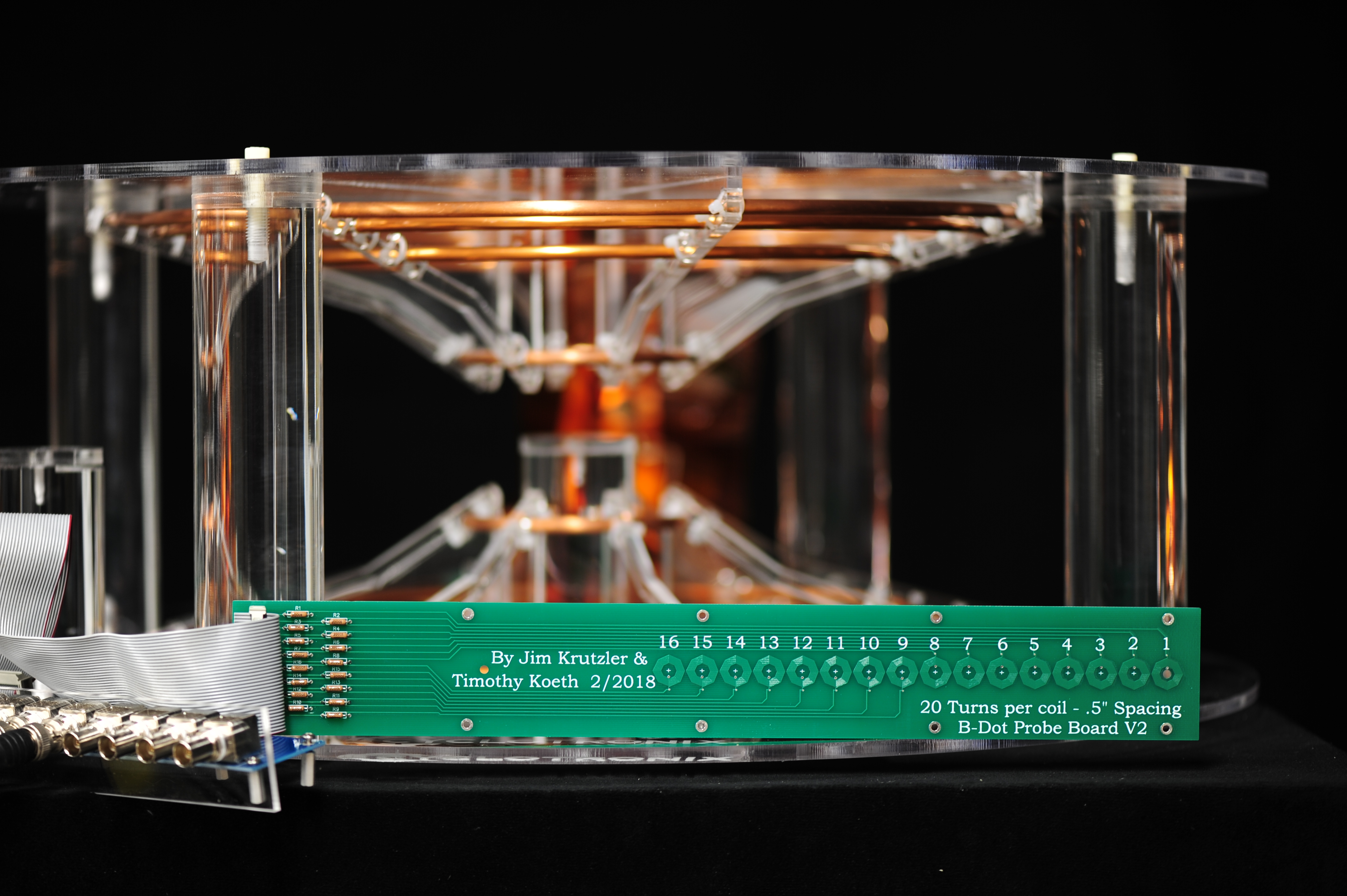
Two B-dot probes were designed. The first version only had 8 pickup coils, each spaced 0.760 inches apart with a total of 100 turns. This turned out to be too coarse a spacing and much too sensitive with 100 turns each – nearly generating 1000 volts during a modest field pulse. A second B-dot probe was developed with 0.500 spacing and 16 coils of only 20 turns which produced a more reasonable voltage.
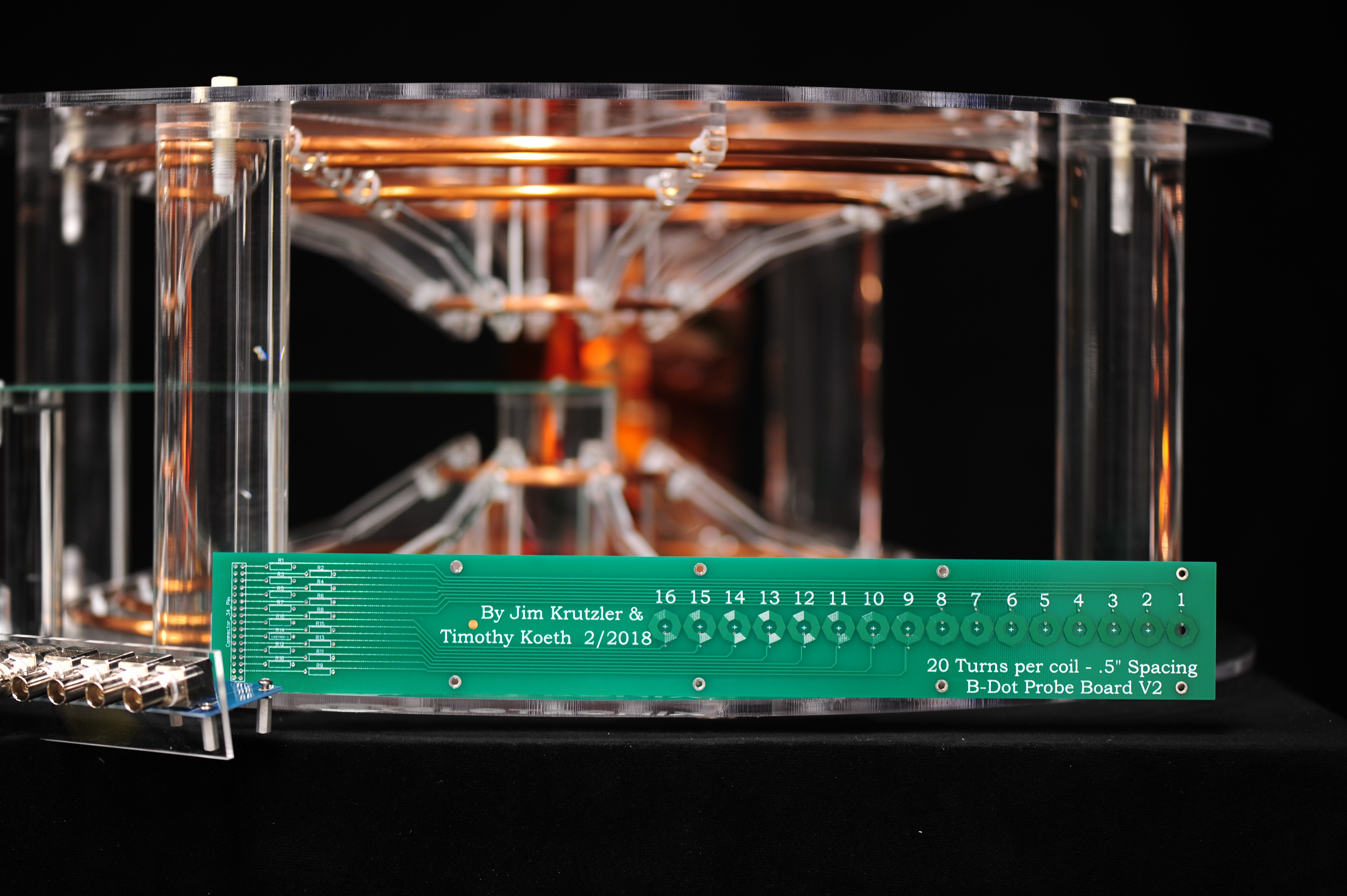
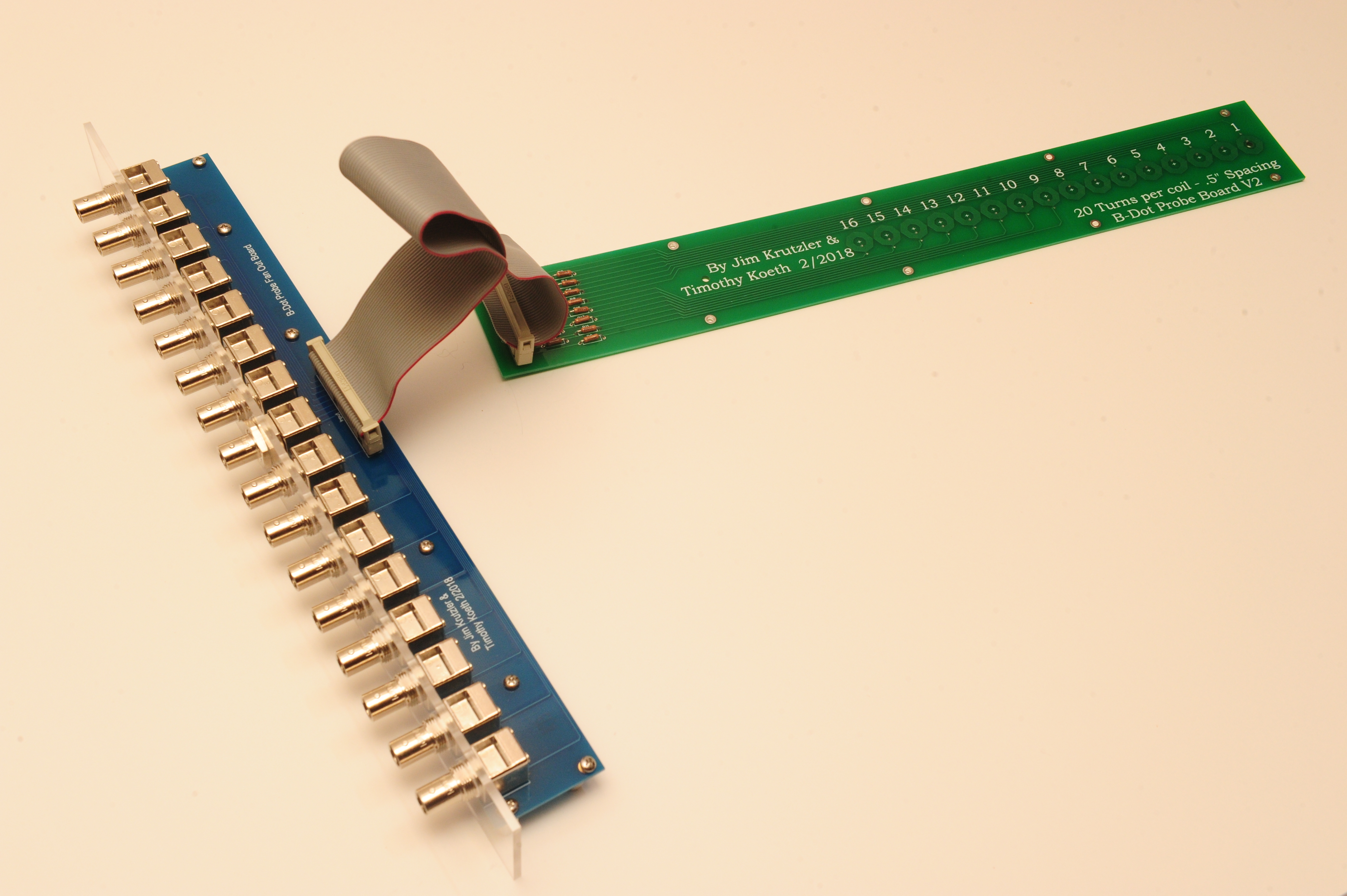
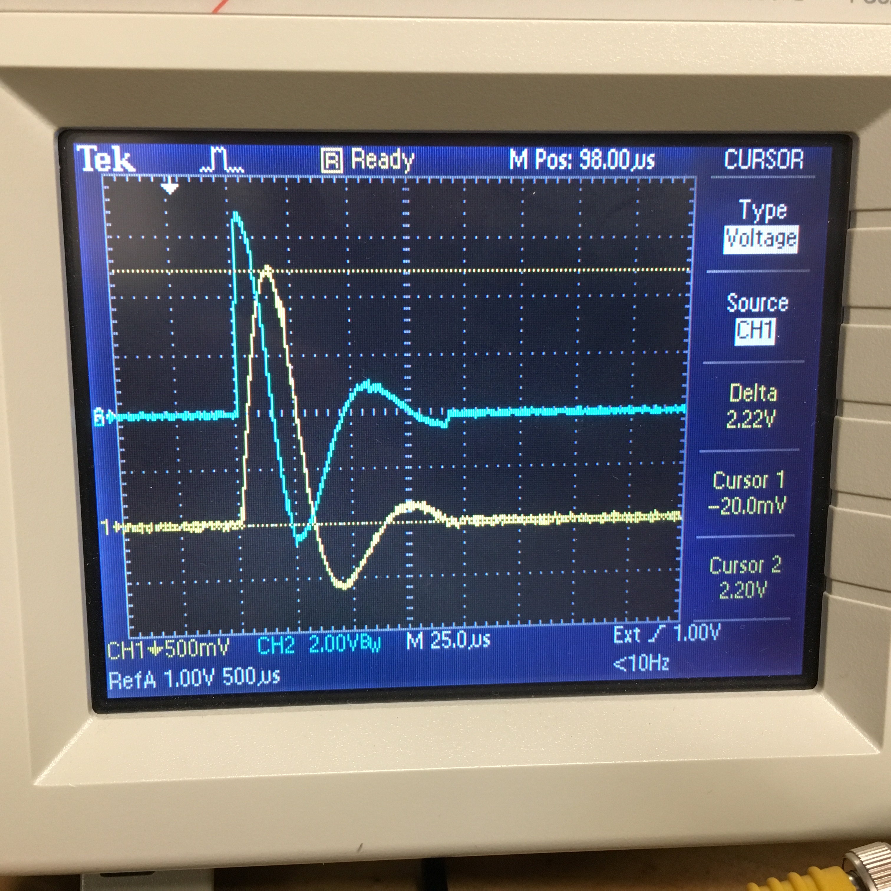
Because of the high density of leads in the second B-dot probe a second, signal fan-out board was necessary, a short ribbon cable interconnects the two. The B-dot board was populated with 16 pickup coils. The data acquisition included four four-channel 100 MHz oscilloscopes for a total of 16 channel of digitization. This was adequate as the 16th coil measured to a radial distance of 190mm more than encompassing the designed equilibrium orbit at 114mm.
Because the measurement campaign was to include 16 channel per shot, and at least 10 shots per increment of vertical former space, an automated data acquisition system was necessary for speed and reliably. A USB-based MATLAB control and acquisition script was written to prepare all four of the oscilloscopes for measurement and perform the data collection post shot.
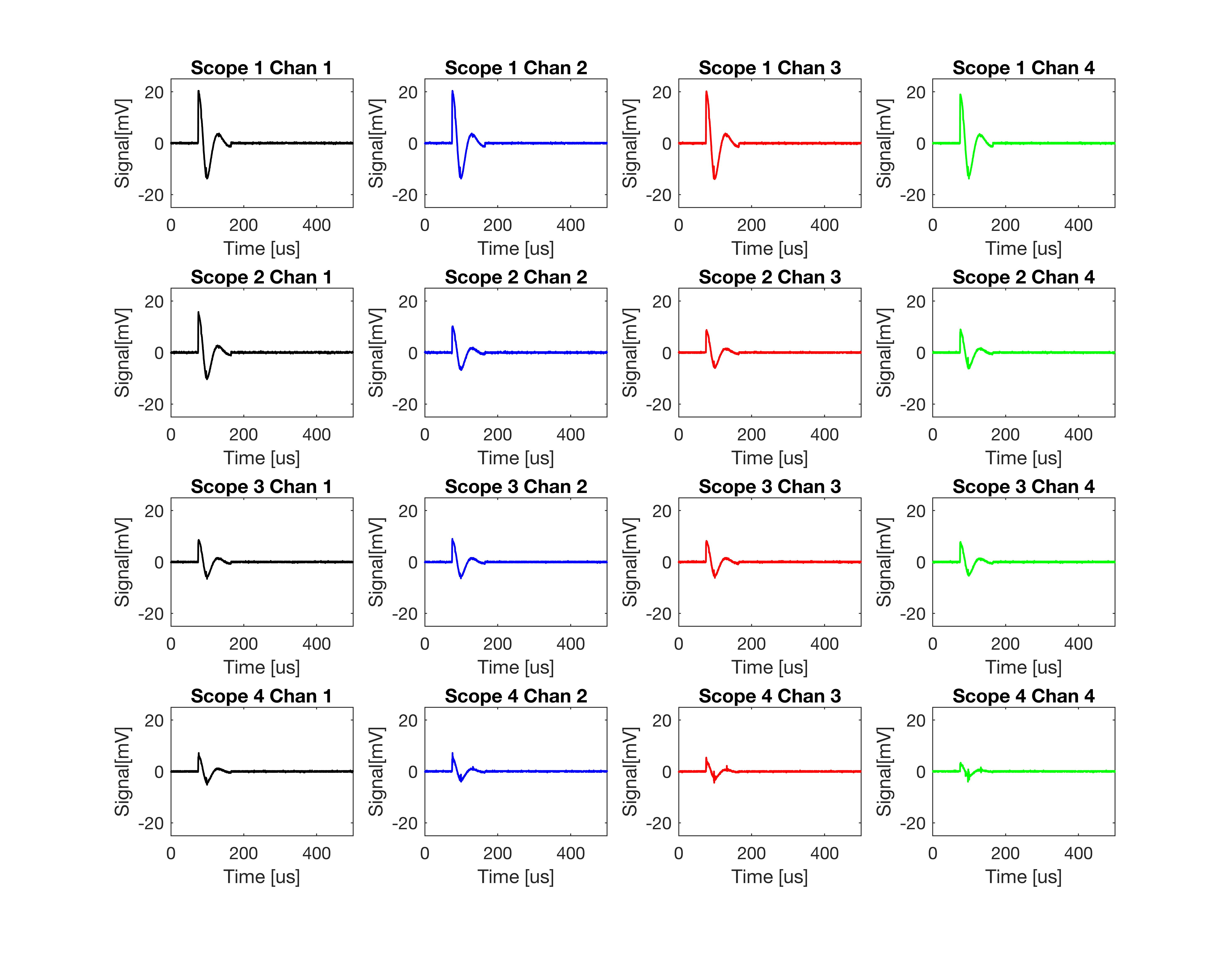
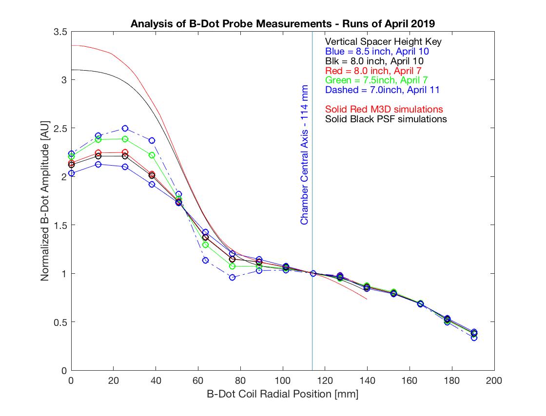
The following plot compares various pulsed B-Dot measurements to the expected field from simulation. The data is normalized to the location of the electron beam orbit. There is a large discrepancy between the simulated fields and the measured profile. Within the experimentally measured profiles there is disagreement too, and this will be the topic of another post.