CW B-Dot Measurement
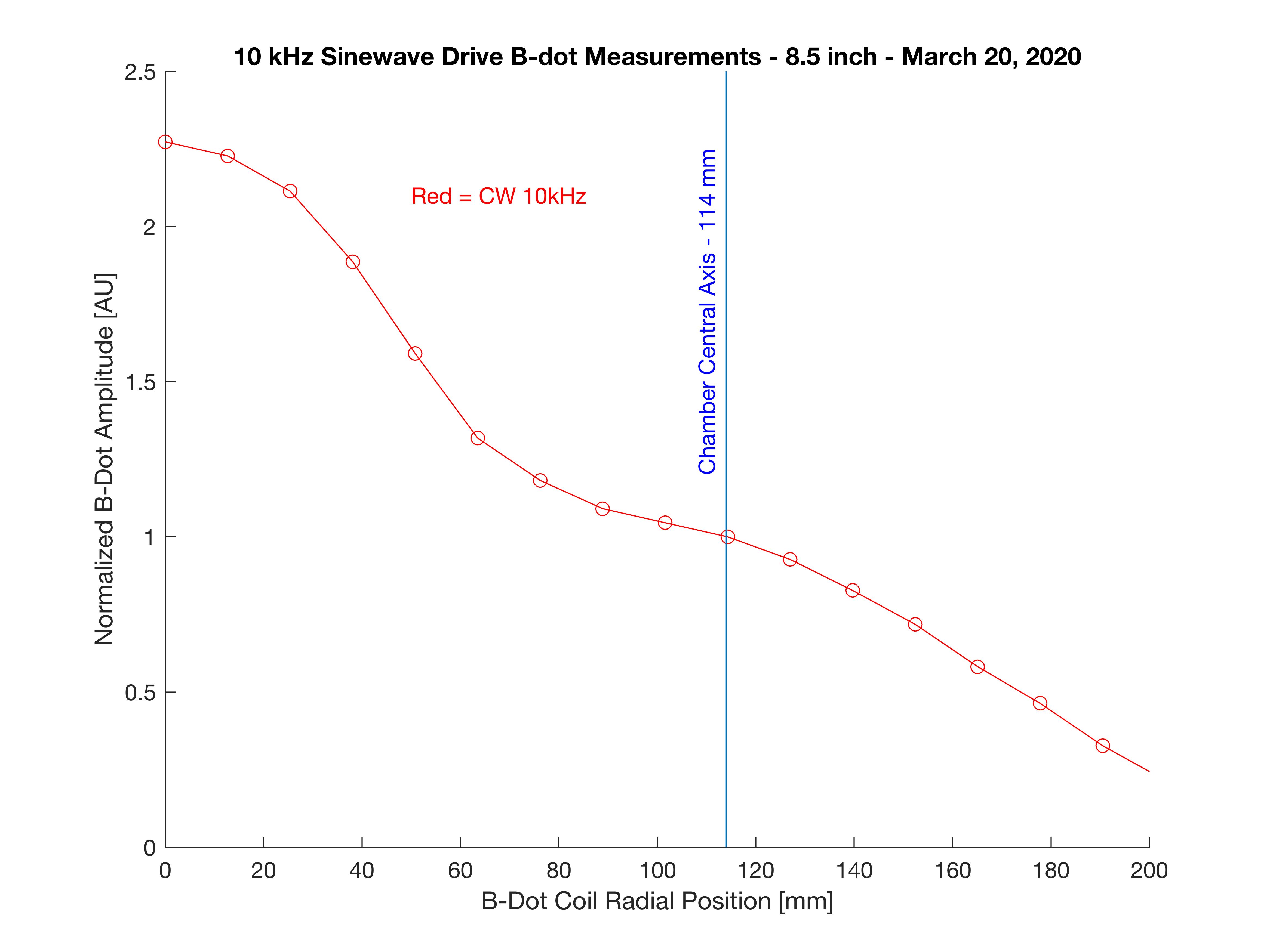
Since the pulsed measurements were challenged with many systematics as well as unknown shot-to-shot variations, I rethought the measurement process. In this approach I drive the betatron coil with a CW sine wave current at 10kHz and draw a pickup coil along a radial path, recording peak-to-peak voltage induced on it.
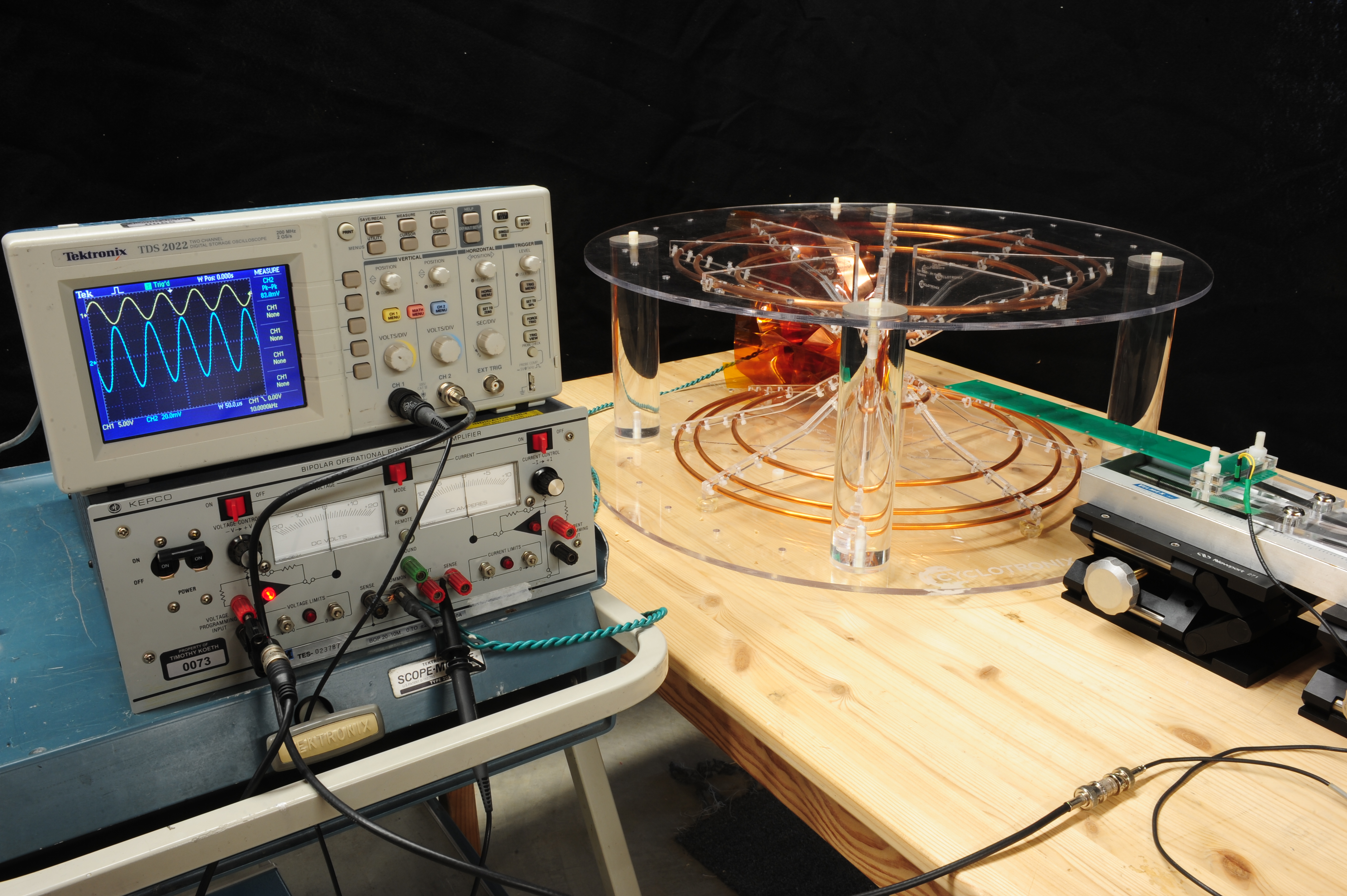
Instead of building yet another B-Dot probe board, I returned to the first PCB B-Dot probe of 100 turns per coil, using only the first coil and leaving the others unterminated. The first coil’s output was connected to the input of a digital oscilloscope with an internal measure function which would automatically track the peak-to-peak voltage of the pickup probe. The oscilloscope was set to average the signals over sixteen sweeps.

The betatron coil’s excitation current was generated by a 10kHz function generator driving a Kepco Bi-Polar operational amplifier for a peak current of approximate 10 Amps through the windings. This current was sufficient to induce up to 200mV voltage on the B-dot winding.
The B-dot probe board was cantilevered off a the carriage of a 11-inch travel, hand driven, Velmex slide. The Velmex slide was mounted to two scissor jacks to position both the vertical hight and inclination of the B-dot probe board. Two heigh gauges were used to align the board to travel in the betatron coil’s median plane.
Data was taken by manually sliding the B-Dot probe along the radial path in 0.5 inch increments and recording the induced voltage each.

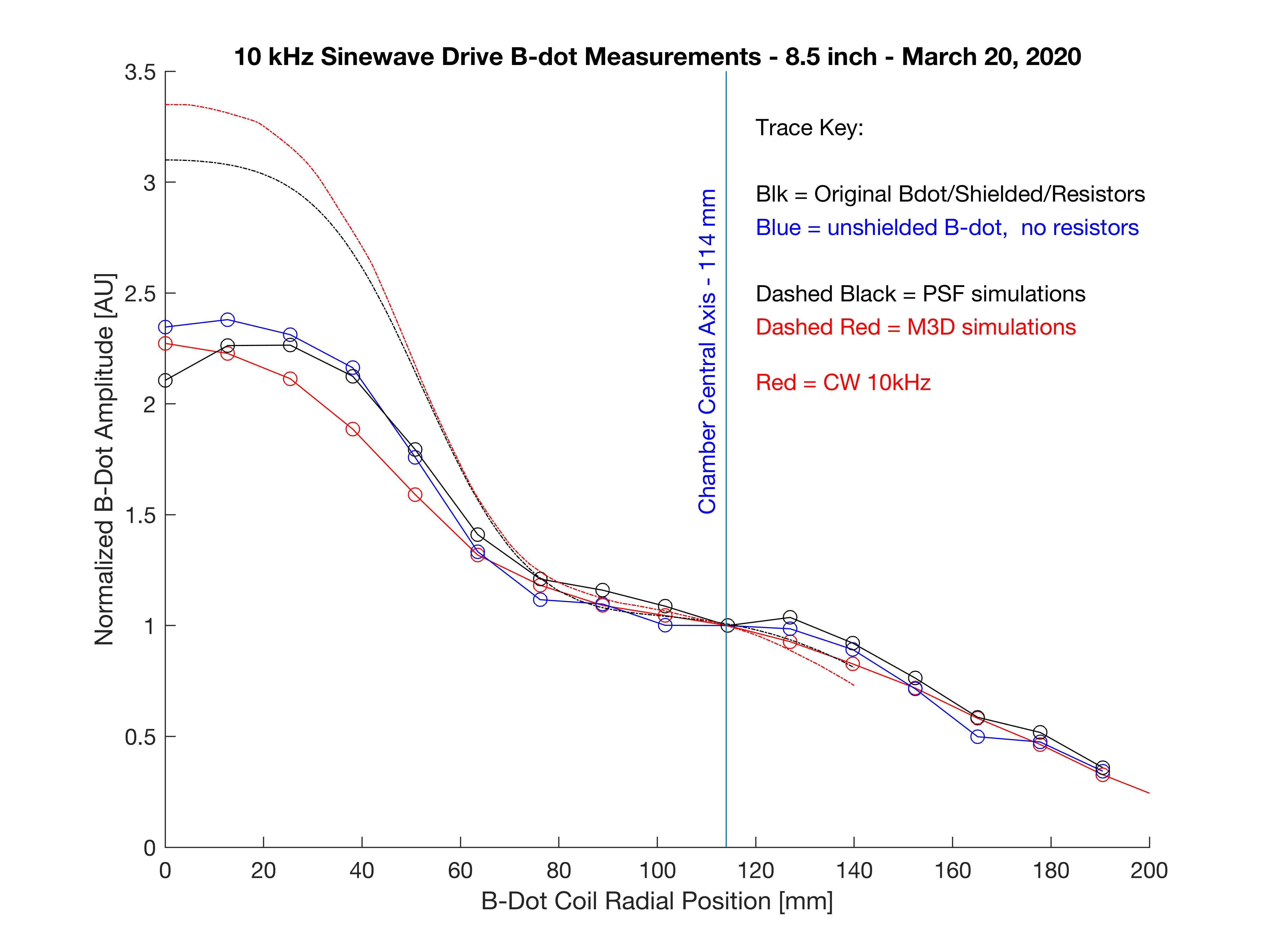
Comparison to previous measurements:

Profile looks correct, but why 2/3 the peak center field? The mystery continues.
